Proven Practices to Prevent Wind Damage
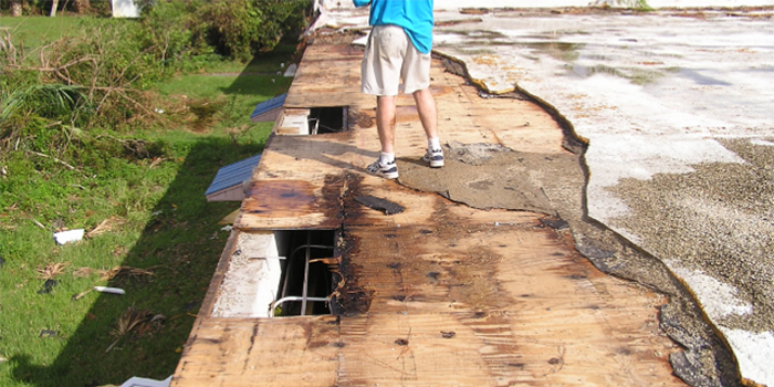

SPRAY FOAM MAGAZINE – The first time witnessing the power of wind, is an eye-opening experience for most in the roofing world. I would estimate that 95 percent or more of all people in the roofing industry have never seen a roof system severely wind damaged, let alone one blown-off by a hurricane. This article will show some real-world examples of wind damaged roofs and provide some basic roof design data and illustrations to better understand the effects of wind forces on low-slope commercial roofs. But more importantly, the author will provide some guidance based upon after-wind event analysis, and field observations, supported by laboratory engineering and required by the International Building Code (IBC) on how to prevent or substantially minimize roof damage during a major windstorm or even a hurricane.
Background
RICOWI (Roof Industry Committee on Weather Issues) found a vast majority of roof damage started with roof edge failure. FM Global cites roof edge damage in 79 percent of 145 cases studied of insurance losses experienced after high wind events.
The Saffir-Simpson Hurricane Wind Scale starts at 74 mph, and while many believe 74 mph winds only occur in the coastal areas, a review of the ASCE Wind Speed Map reveals inland California, New York, North Carolina, and Oregon, as well as Arizona, Colorado, Idaho, Montana, Nevada, New Mexico, Vermont, Washington, and Wyoming all have inland zones where wind speeds can exceed 74 mph.
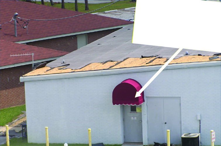
How is it possible that wind could rip off the leading edge of the roof shown in FIGURE 1, and yet the canvas canopy over the door remained intact, undamaged?
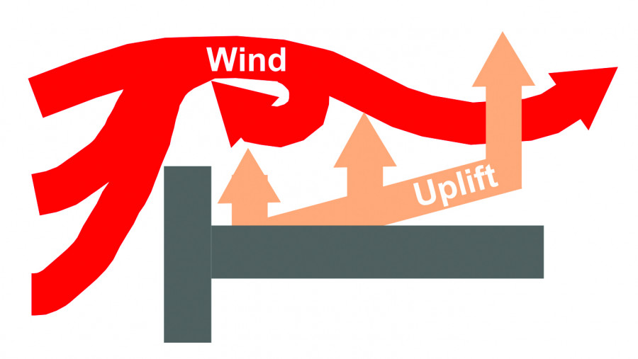
As shown in FIGURE 2, when the wind hits a building wall, it is deflected up over the top of the building as well as around the sides. As wind passes over the top edge of the building, negative pressure is developed creating a negative pressure (vacuum-like effect), known as the Bernoulli Principle, lifting the edge of the roof. A parapet wall less than three feet high enhances the negative pressure at the edge as shown in FIGURE 3.
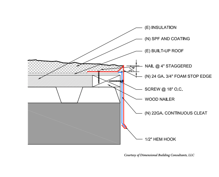
The IBC Chapter 15, 1504.6 requires the following:
“Metal edge systems, except gutter and counterflashing, installed on built-up, modified bitumen, and single ply roof systems having a slope less than two units vertical in 12 units horizontal (2:12) shall be designed and installed for wind loads in accordance with chapter 16 (Structural Design) and tested for resistance in accordance with Test Methods RE-1, RE-2 and RE-3 of ANSI/SPRI ES-1 except the basic wind speed shall be determined from Fig. 1609.3 (1) through (12) as applicable.” While SPF is not listed in this paragraph, know that the provisions apply equally in the eyes of the Building Officials.
This typically requires that the existing edge flashing is removed when installing new edge flashing.
A little closer look into ANSI/SPRI ES-1 shows that it is a reference for those who design, specify, or install edge materials used with low-slope roofing systems (e.g., Roofing Contractors). It addresses horizontal roof edges and copings. The following factors are considered when designing a roof edge:
Structural integrity of the substrate that anchors the edge (e.g., nailers)
Wind resistance of the edge detail
Materials specifications
Key factors used in ANSI/SPRI ES-1 to determine the loads on a roof edge are:
- Wind Speed
- Building Occupancy
- Building Height
- Location of the edge device
- on the roof
- Building Location
The following information is provided as “guidelines” for consideration when roofing in high wind zones. Calculations for any specific roof can be performed using the NRCA Roof Wind Designer at roofwinddesigner.nrca.net.
Fastening
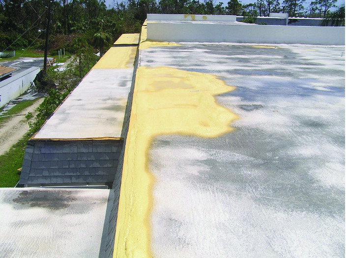
Logically, the roof blow-off starts at the edge. If the edge flashing is not fastened properly, it will be the first part of the roof to be damaged and likely lead to peeling of the adjacent roof interior. As shown in FIGURE 4, several sections of edge flashing were blown off, while most of the roof remained intact. Examination of the blown-off metal flashing on the ground revealed that the metal was fastened at more than 12 in, and often at 16 in, instead of the required 4 in staggered in a diagonal pattern. Had the metal flashing been properly fastened, this SPF roof would have not been damaged.
Unfortunately, the SPF roof applied over a gravel BUR (built-up roof) with plywood deck shown in FIGURE 6, suffered severe wind damage at the leading edge. Aside from the few sections of plywood blown out, (due to interior pressurization) it was determined that the BUR was originally improperly fastened to the plywood deck, and the gravel stop metal edge was also not properly fastened. The key point for SPF roof applicators, DO NOT assume the attachment of the existing flashing and roof membrane is adequate.
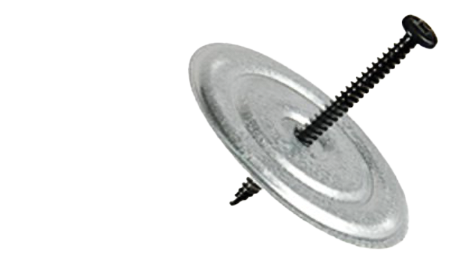
Had the SPF contractor simply added additional screws with 3-in steel disks in a pattern of two to four screws/disks per every square foot along the 10-ft perimeter, this damage could have been limited to the metal edge flashing. Whatever fastening pattern is used along the 10-ft edge, should be doubled at the 10 x 10 corners as wind pressures are increased at corners.
It is field tested and proven that SPF roofing has superior adhesion in hurricane wind events. To achieve complete success, when applying SPF roofing in a known high-wind area, replace the edge flashing with a new continuous cleated system. Consider adding additional screws and disks to the 10-ft perimeter of the existing roofing and doubling the fastening pattern in the 10-ft corners. This will ensure the superior performance of the new SPF roof system through many years of windstorms.
Robb Smith is an IIBEC Registered Roof Consultant and a SPFA Field Examiner, with over 40 years in the roofing industry.
For use by SprayFoamMagazine.com & Spray Foam Magazine
Disqus website name not provided.


